Voxengo HarmoniEQ
Primary User Guide (PDF): English, Français, Deutsch, Русский язык
Applications
- Audio mastering equalizer
- Dynamic equalizer
- Harmonic enhancer
- Stereo, mono, mid-side equalizer
- 7.1, 5.1 surround sound equalizer
- FFT spectrum analyzer (SPAN-like)
- “Character” equalizer
- “Tube equalizer”
- Classic Lampthruster enhancer
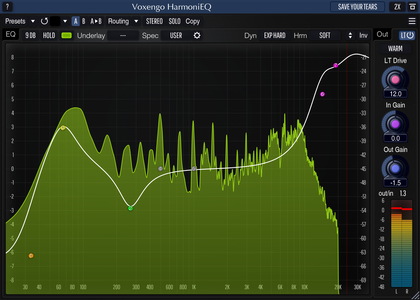
HarmoniEQ is a parametric, harmonically-enhanced equalizer AAX, AudioUnit, and VST plugin for professional music production applications. Harmonic enhancement HarmoniEQ applies to the sound is an inherent element of its overall sonic quality. HarmoniEQ also features dynamic equalization modes that offer you a vast palette of sound-shaping capabilities, suitable for mastering. Beside that, HarmoniEQ features a saturation module of the original “Lampthruster” algorithm which produces a unique, impactful, sonic character.
Since the easiness of tuning was one of our goals when producing this plugin, HarmoniEQ features a single control surface to specify the equalizer curve. HarmoniEQ's control surface workflow implements our best findings in the area of “user-equalizer” interaction. Just drag the filter control points to the right places. You can enable up to 7 parametric filters, with the filter type freely-selectable from peaking, low-shelf, high-shelf, low-pass, high-pass, and notch filter types.
Another useful element of HarmoniEQ is its control surface's frequency range which goes up to 38 kHz. Such extended range allows you to make smooth “air” boosts easily. While HarmoniEQ is best suited for boosts, its cuts also sound great.