Making rooms
Have you ever wondered when--JUST WHEN--a synthetic software or
hardware reverb will sound like a real reverberating space?
You may be wondering why it happens that even a
"recorded-for-real" reverb impulse run through a convolving
reverberator most of the time sounds duller than a real space
it is aimed at reproducing? We do not know the answer for sure.
BUT facing the same questions, we have tried to find SOMETHING that
could please us. And we have FOUND THAT THING. It is the Impulse
Modeler that imprints reverberation into a universal impulse
response file that can be used with any convolution
reverberator available. The most important thing is that the Impulse
Modeler ACTUALLY WORKS, while being just a 2D tool. The created
reverbs are so dense and convincing that they can even compete
with recorded reverberant spaces. Software and hardware
reverbs most of the time do not even come close. After you
have applied a professionally designed Impulse Modeler reverb
to any sound, you will not know for sure whether that sound
was recorded in a real room or if its reverb was emulated.
"Professionally designed" here does not mean it is hard to
design good reverbs. Actually, designing a good reverb is
easy after you get the feel of Impulse Modeler. Later,
everything will depend only on your imagination; Impulse
Modeler will embody your ideas precisely.
We want to emphasize that Impulse Modeler is an artistic
tool. It was designed mainly for musicians, sound designers
and sound engineers. If you are looking for reverbs not available
anywhere that are maximally convincing and easily
controllable, Impulse Modeler is the tool for you.
The program itself was designed in a fashion to provide all the
necessary information while you are in the process of
reverb design. Almost every controllable element has a
brief description below it. This help file
contains in-depth information on features of the Impulse Modeler.
Getting started
To get started with Impulse Modeler we suggest you to load any existing
demo design bundled with the program. To do so you should press the
"Load" button in the "File Options" box on the bottom left side
of the user interface. Please note that designs are stored in the
"designs" folder. The full default path to this folder is
"\Program Files\Voxengo\Impulse Modeler\designs\".
After the design is loaded its geometry will be immediately displayed.
You can examine the geometry screen to see how the design has been built.
Please read this manual further to understand the various objects present on
the geometry screen.
You should also understand that Impulse Modeler is not a plug-in which
can be loaded in the audio host application. Impulse Modeler is a standalone
Windows application that creates WAV file which can be loaded by any existing
convolution program like SIR or Acoustic Mirror.
So, after the design is loaded you can generate a WAV file out of it.
Simply press the "Generate" button and specify the folder and the name
of the resulting WAV file. Later you should use this folder and the name
when loading the generated WAV file in your reverb plug-in.
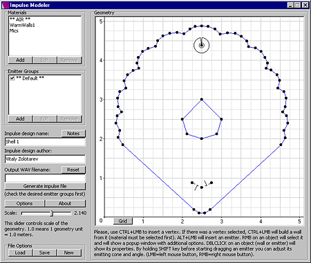
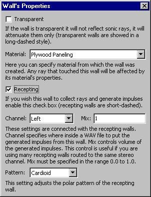
Vertices and walls

This image depicts vertices (black dots) and walls that
represent building blocks of a room's geometry. The walls have
different colors because they have different materials
assigned to them.
You can create vertices by holding the CTRL key on the
keyboard and pressing the left mouse button (LMB).
Vertices can be deleted by first selecting and then
pressing the right mouse button (RMB). A pop-up window will
appear, allowing the selected vertex to be deleted.
Any walls connected to the vertex being deleting will also be
deleted.
Selection of any object on the geometry screen is accomplished by
clicking on it with the left mouse button.
Walls can be created swiftly. After a new vertex is inserted,
it will be automatically selected. When you add a
next vertex without deselecting a previous one, a wall will
be created between these two vertices. But before this starts
to work, you must first select a material which you want to
assign to all newly created walls. After that is
accomplished, you can create wallforms of any complexity just
by clicking your way on the geometry window while holding
the CTRL key down.
Walls between existing vertices can be built the same way.
First, you need to select the starting vertex and then
hold the CTRL key click on the ending vertex.
When a wall is selected and you press the LMB, you will see a
pop-up window allowing the deletion of a wall or adjustment of its
properties. Double-clicking on a wall also brings up its
properties window.
Emitter

This picture shows an emitter heading up. Its emitting cone
has a span of roughly 120 degrees.
To create a new emitter, you have to hold the ALT key and
press the left mouse button in the desired position in the
geometry window. To adjust the emitter's heading and cone, you
have to hold the SHIFT key and drag the emitter with the left
mouse button. Horizontal mouse movement then will adjust
the emitter's heading, while vertical movement will adjust its
emitting cone.
If you press the right mouse button on an emitter, a pop-up
window will appear allowing either the deletion of the selected emitter
or adjustment of its properties. Double-clicking on an emitter will
also bring up its properties.
Emitter's properties
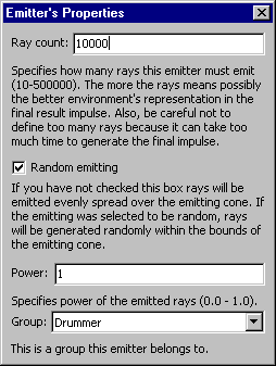
Random emitting here means that all rays generated by this
emitter will be emitted in random directions within the bounds
of the emitting cone. Enabling or disabling this option can
be used to get different spatialization results.
The Power setting allows you to specify the "significance"
of an emitter. If you are
using only a single emitter in the room design, the power setting
is not really meaningful. But if you have several emitters
with equal number of rays assigned to them, an emitter with
greater power will affect the resulting impulse file more than
the others.
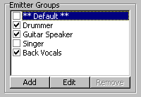
The Group list allows you to select emitter group this emitter
belongs to.
Materials
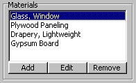
This window on the main screen lists all materials available
in the current design. The currently selected material (which will
be assigned to all newly created walls) is highlighted with a
blue bar. You can double-click a material's name to edit
the properties of this material. Alternatively, you can select
the desired material and press the "Edit" button.
The "Add" button is used to add a new material. After a new
material has been added, it will have a name in the form of
"unnamedX" assigned to it. You can edit this name later in the
material editor. Material names must be unique.
The "Remove" button is enabled only if the currently selected
material is not used anywhere in the room design.
Before you can delete the selected material, you have to unassign
it from all walls where it was used.
A special "** AIR **" material defines properties of the
surrounding air. Frequency-dependant air damping and sustain parameters are
defined `per 75 meters'.
Material editor
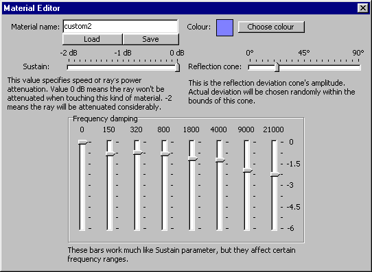
This is a material editor window. The name edit box can be used
rename a material. The Color box
specifies the material's color as it is shown in the geometry window.
The "Load" and "Save" buttons allow you to load and save the current
material. Materials are stored in files with an ".imm" extension.
The sustain, reflection cone and frequency damping parameters
specify how an emitted ray is affected by this material.
During impulse file generation, every time a ray touches a wall
with this material assigned to it, a ray's parameters will be
adjusted according to the specified material settings.
Sustain affects the general power of a ray, without frequency
dependance.
Reflection cone allows a ray to reflect from the wall's surface
with a random deviation. This mainly affects spatialization
structure and can be used for additional design tweaking.
This setting has another meaning of 'surface roughness'. For
example, to get a feeling of a carpet-like material, a value
close to 90 degrees must be specified. To get some kind of
metallic or glass material, a value close to 0 degrees must be
specified.
Frequency damping is mostly the same as Sustain parameter,
but it is defined for each spectral band. The numbers above the
sliders are defined in Hertz.
Generate button
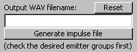
Here you can enter an output filename for the generated impulse
file. If you press the "generate" button while the filename edit
box is clear, a "save as" dialog will be shown allowing you to
select a path and a filename for the generated impulse file.
If the edit box is not empty, impulse generation will start
immediately, overwriting any existing file with the same name
without any notice. The "Reset" button can be used to clear
the filename edit box.
An unregistered version of the Impulse Modeler allows a limited number of
impulse generations per program's session.
Options
A window size of 100-200 is adequate
for sample rates up to 48 kHz. If the sample rate is higher,
a higher window size is required to get good results. A larger
window size must be used also if your design has materials with a high
damping of low frequencies. Window Type is a rather experimental option,
so you'll have to try different types to find the most suitable
one. A generally acceptable window type is "cos^2".
Note on "Density" setting: even if this option can be used
to make a resulting impulse response more dense, it performs this in a
"fake" manner, inserting data in between actually calculated
impulses, so density in some cases can decrease the overall
realism of the impulse.
Minimal ray power control can be used to slightly boost
the impulse calculation speed. Since every ray generated by an
emitter is calculated until its power becomes less than
this value, by adjusting this value you can make the Impulse
Modeler skip any unnecessary calculation cycles.
Sync reverb tail is a rather useful option if you want to
achieve the most convincing spatialization. This option is
enabled by default. The Impulse Modeler calculates the
shortest distances for all emitter-receptor pairs and uses the
smallest found value as an offset. This option can be disabled if
your room design is something very special, containing several rooms
and many emitters and recepting walls. For normal rooms with a
single emitter and a pair of recepting walls, enabling this option
is useful. Without this option enabled, the calculated impulse will
be trimmed to the time of the first spike appeared in the impulse,
allowing to get rid of the unnecessary leading silence.
The "Direct Signal Level" option enables the generation of the
direct (dry) impulse spikes. Please note that when this
option is enabled "Sync reverb tail" option will be ignored
and the impulse file would not be trimmed in any way.
The "Manual Normalize" option can be used if you do not want the
auto-normalization to be performed on the generated impulses. Manual
normalization is useful when generating several impulses using the same
design that should preserve inter-impulse level relations.
This in most cases means that you have not put any recepting
walls (showed with dashed lines), or you have not put any
emitters, or emitter's rays do not touch any recepting wall
at all.
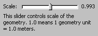
The numbers represent geometry units.
If scaling is 1, numbers represent 1, 2, 3 meters, if scaling
is 5, numbers represent 5, 10, 15 meters, etc.
It was determined that a room's height can be controlled with the Sustain
parameter of the material. Exact height is a very hard thing to
perceive in the real world, but the Sustain parameter works
very close to some kind of a height controller. Of course, its
setting will be relative to the overall room geometry and used
scale.
Yes, this is right. However, these recepting walls are not
necessarily "microphones", because they do not try to emulate
any properties specific to microphones.
There is no way to use it 'correctly'. Theoretically, all
values are equal. This setting was added for additional
tweaking. For example, you can try 3-4 random seed values and
choose the one that sounds best. In fact, the general quality must
not change at all, only spatialization and color changes
with random seed.
If you are using only a single emitter, 'power' field has no
real sense. But if you have several emitters, you can balance
power between them using this field.